Topologia Paso a Paso Cisco Packet tracer para 3 Sucursales LAN WAN Enrutamiento Estatico y Dinamico RIP con VLANs, Servidor DHCP, Router DHCP, Vlan administracion


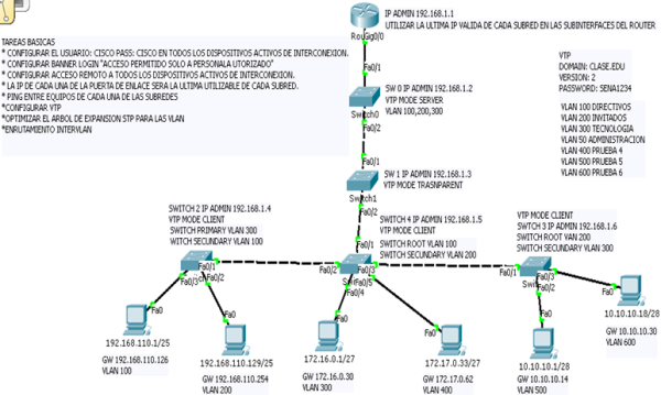
Se debe diseñar e implementar una red que cumpla los siguientes requerimientos:

topologia

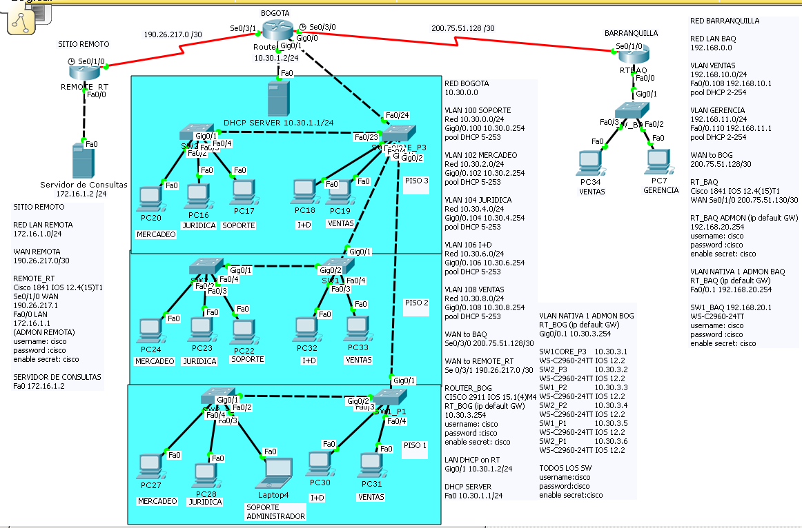
Oficina Principal Bogota:

  • Ubicada en Bogota
  • 5 Redes: Mercadeo (10 Equipos), Juridica (5 Equipos), Soporte (30 Equipos) I+D (10 Equipos), Ventas (20 Equipos)
  • Las redes estan distribuidas en tres pisos. En cada piso hay al menos un equipo de cada red.
  • Conectada con la oficina remota por medio de un enlace WAN de 512K.

Oficina remota:

  • Ubicada en Barranquilla
  • Las redes de bogota son independientes de las redes de Barranquilla
  • 2 Redes: Ventas (5 equipos), Gerencia (3 equipos).

Tenga en cuenta:

  • Se asume que la red tendra un crecimiento estimado del 10% en los proximos 5 años.
  • Implementar RIP
  • La oficina principal tiene su propio servidor DHCP (Servidor DHCP, Conectado directamente a una interfaz del router).
  • La oficina remota (BAQ) tiene su propio servidor DHCP (Router DHCP).
  • En bogota existe un enlace WAN hacia un sitio remoto de confianza donde hay un servidor de consulta. Bogota alcanza la red donde se encuentra este servidor a trave de una ruta estatica.
  • Verifique que todos los equipos tienen acceso al servidor de consulta.
  • El administrador de la red debe poder hacer TELNET a cualquier equipo de la infraestructura de la red interna (Routers y Switches).
  • Confgure adecuadamente todos los equipos.
  • Documente detalladamente la red:
  • Direccionamiento IP, Puertos utilizados, referencias de Routers, Switches e IOS usados.

_________________________________________________________________________

CONFIGURAMOS NUESTRO ROUTER DE BOGOTA:

hostname Router_BOG

enable secret cisco

username cisco password 0 cisco

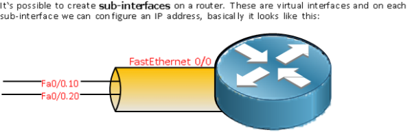
CREAMOS LAS VLAN 100 102 104 106 Y 108 EN LA VLAN DATABASE DEL ROUTER CON EL FIN DE QUE EL ROUTER PUEDA USAR EL TRAFICO ETIQUETADO QUE USAN LAS SUBINTERFACES.

Router_BOG#vlan database

% Warning: It is recommended to configure VLAN from config mode,

as VLAN database mode is being deprecated. Please consult user

documentation for configuring VTP/VLAN in config mode.

Router_BOG(vlan)#vlan 100 name vlan100

VLAN 100 added:

Name: vlan100

CONFIGURAMOS LA INTERFAZ GigabitEthernet0/0 QUE CONECTA A NUESTRO SWITCH PRINCIPAL DE LA RED LAN

interface GigabitEthernet0/0

no ip address

(CON ESTE COMANDO DE NO IP ADDRESS NO LE ASIGNAMOS UNA IP A LA INTERFAZ FISICA LO QUE NOS PERMITE CREAR LA SUB INTERFACES)

CREAMOS LA SUBINTERFAZ PARA LA VLAN DE ADMINISTRACION (VLAN NATIVA)

interface GigabitEthernet0/0.1

encapsulation dot1Q 1 native

ip address 10.30.3.254 255.255.255.0

CREAMOS LAS SUBINTERFACES DE CADA VLAN DE LA LAN PARA EL ENRUTAMIENTO INTER VLAN Y ENRUTAMIENTO WAN.

EJECUTAMOS EL COMANDO ENCAPSULATION DOT1Q MAS EL NUMERO DE LA VLAN

USAMOS EL COMANDO IP HELPER-ADDRESS EN CADA SUBINT PARA REDIRECCIONAR LAS PETICIONES DHCP HACIA EL SERVIDOR DHCP A CONFIGURAR.

interface GigabitEthernet0/0.100

encapsulation dot1Q 100

ip address 10.30.0.254 255.255.255.0

ip helper-address 10.30.1.1

!

interface GigabitEthernet0/0.102

encapsulation dot1Q 102

ip address 10.30.2.254 255.255.255.0

ip helper-address 10.30.1.1

!

interface GigabitEthernet0/0.104

encapsulation dot1Q 104

ip address 10.30.4.254 255.255.255.0

ip helper-address 10.30.1.1

!

interface GigabitEthernet0/0.106

encapsulation dot1Q 106

ip address 10.30.6.254 255.255.255.0

ip helper-address 10.30.1.1

!

interface GigabitEthernet0/0.108

encapsulation dot1Q 108

ip address 10.30.8.254 255.255.255.0

ip helper-address 10.30.1.1

CONFIGURAMOS LA INTERFAZ QUE CONECTARA AL SERVIDOR DHCP

interface GigabitEthernet0/1

ip address 10.30.1.2 255.255.255.0

duplex auto

speed auto

CONFIGURAMOS LA INTERFAZ SERIAL WAN QUE CONECTARA CON LA SUCURSAL DE BARRANQUILLA CON EL BANDWITH CORRESPONDIENTE:

interface Serial0/3/0

bandwidth 512

ip address 200.75.51.129 255.255.255.252

clock rate 2000000

CONFIGURAMOS LA INTERFAZ SERIAL WAN QUE CONECTARA CON EL SITIO REMOTO DE CONFIANZA

interface Serial0/3/1

ip address 190.26.217.2 255.255.255.252

!

interface Vlan1

no ip address

shutdown

CONFIGURAMOS EL ENRUTAMIENTO DINAMICO PARA LA SEDE DE BARRANQUILLA, ANUNCIANDO LAS REDES DIRECTAMENTE CONECTADAS EXCEPTO LA RED DEL SITIO REMOTO Y APLICAMOS EL COMANDO (REDISTRIBUTE STATIC) PARA QUE COMPARTA EL ENRUTAMIENTO ESTATICO DEL SITIO REMOTO DE CONFIANZA, CON EL FIN DE QUE LA RED DE BAQ ALCANCE EL SERVIDOR DE CONSULTAS.

router rip

redistribute static

network 10.0.0.0

network 200.75.51.0

CREAMOS LA RUTA ESTATICA HACIA LA RED DEL SERVIDOR DE CONSULTAS EN EL SITIO REMOTO

ip route 172.16.1.0 255.255.255.0 190.26.217.1

CONFIGURAMOS LOS ACCESSOS POR VTY, CON USUARIO Y PASSWORD ENCRIPTADO Y EL RESPECTIVO BANNER.

banner login ^Ctbogota

<<**BIENVENIDO RONALD REALES BOGOTA**>> ^C

line vty 0 4

password cisco

login local


ESTA ES LA TABLA DE ENRUTAMIENTO QUE TENDRA BOGOTA AL FINAL DEL EJERCICIO:

Capture


CONFIGURAMOS NUESTRO SERVIDOR DHCP EN EL PACKET TRACER 

Capture
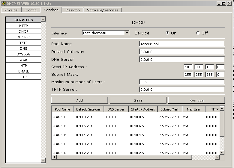
Aqui configuramos las VLANs con sus respectivos Pools de direcciones, recordemos que cada vlan debe tener con Default Gateway la direccion IP de la subinterfaz en el Router de Bogota.

Capture

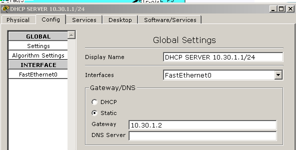
Recordemos que este servidor DHCP virtual debe tener como Gateway la direccion IP LAN del Router de Bogota.


CONFIGURAMOS NUESTRO SWITCH CORE UBICADO EN EL PISO 3

hostname SW1CORE_P3

enable secret cisco

username cisco privilege 1 password 0 cisco

CREAMOS TODAS LAS VLAN QUE USA LA RED DE BOGOTA

SW1CORE_P3(config)#vlan 102

SW1CORE_P3(config-vlan)#name 102

SW1CORE_P3(config-vlan)#exit

CONFIGURAMOS EL PUERTO ETHERNET EN MODO ACCESO DE UN EQUIPO PERTENECIENTE A LA VLAN 106 (I+D) DE ACUERDO A NUESTRO DIAGRAMA

interface FastEthernet0/3

switchport access vlan 106

CONFIGURAMOS DE ESTA MANERA LOS PUERTOS DE ACCESO CORRESPONDIENTES A CADA EQUIPO DE LA VLAN A LA QUE PERTENECERA


CONFIGURAMOS EN MODO TRUNK EL PUERTO FAST ETH 0/24 QUE SE CONECTARA CON UNA DE LAS INTERFACES LAN DEL ROUTER DE BOGOTA, CON EL FIN DE QUE TODO EL TRAFICO ETIQUETADO DE LA LAN PUEDA SER ENRUTADO A LA MISMA LAN (INTERVLAN) Y A LA WAN.

interface FastEthernet0/24

switchport mode trunk

CONFIGURAMOS LA VLAN DE ADMINISTRACION CON SU IP CORRESPONDIENTE

interface Vlan1

ip address 10.30.3.1 255.255.255.0

CONFIGURAMOS EL DEFAULT GATEWAY PARA EL TRAFICO DE ADMINISTRACION DEL SWITCH CON EL FIN DE ADMINISTRARLO REMOTAMENTE DESDE CUALQUIER RED, EN ESTE CASO ES LA SUBINTERFAZ DE ADMON CREADA EN EL ROUTER DE BOGOTA.

ip default-gateway 10.30.3.254

CONFIGURAMOS LOS ACCESSOS POR VTY, CON USUARIO Y PASSWORD ENCRIPTADO Y EL RESPECTIVO BANNER.

banner motd ^C <<<<<****BIENVENIDO AL SW CORE****>>>>>> ^C

line vty 0 4

login local


CONFIGURAMOS LOS DEMAS SWITCHES DE LA RED LAN DE BOGOTA TENIENDO EN CUENTA QUE LAS CONEXIONES ENTRE LOS SW DEBEN SER CON INTERFACES TRONCALES PARA TRAFICO INTERVLAN Y LOS PUERTOS QUE CONECTAN A LOS RESPECTIVOS USUARIOS DEBEN ESTAR EN MODO ACCESO DEPENDIENDO DE LA VLAN A LA QUE PERTENEZCAN.

NO OLVIDEN CONFIGURAR LAS VLAN EN CADA SW.

RESUMEN DOCUMENTACION IP EQUIPOS BOGOTA: 

Capture


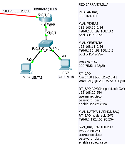
CONFIGURACION ROUTER DE BARRANQUILLA

hostname RTBAQ

enable secret cisco

CREAMOS TODAS LAS VLAN QUE USA LA RED DE BARRANQUILLA.

RTBAQ(config)#vlan 102

RTBAQ(config-vlan)#name 102

RTBAQ(config-vlan)#exit

COMO ESTE ROUTER VA A TENER LA FUNCION DHCP PARA LOS EQUIPOS DE LA LAN CONFIGURAMOS LAS DIRECCIONES IP QUE VAN A SER EXCLUIDAS DEL POOL DHCP DE CADA VLAN (VENTAS Y GERENCIA) EN ESTE CASO LAS DIRECCIONES DE LAS SUBINTERFACES A CREAR EN LA INTERFAZ FAST ETHERNET 0/0

ip dhcp excluded-address 192.168.10.1

ip dhcp excluded-address 192.168.11.1

CREAMOS LOS POOL DHCP CORRESPONDIENTES A CADA VLAN Y SU DEFAULT ROUTER PARA ENRUTAMIENTO DE TRAFICO (DEBEMOS CREAR PRIMERO LAS SUBINTERFACES CORRESPONDIENTES EN EL ROUTER)

ip dhcp pool ventas

network 192.168.10.0 255.255.255.0

default-router 192.168.10.1

ip dhcp pool gerencia

network 192.168.11.0 255.255.255.0

default-router 192.168.11.1

CONFIGURAMOS LAS SUBINTERFACES EN LA LAN DEL ROUTER

interface FastEthernet0/0

no ip address

CONFIGURAMOS LA SUBINTERFAZ DE LA VLAN DE ADMON DEL ROUTER

interface FastEthernet0/0.1

encapsulation dot1Q 1 native

ip address 192.168.20.254 255.255.255.0

CONFIGURAMOS LAS SUBINTERFACES PARA LAS VLAN DE BAQ EN INTERFAZ LAN DEL ROUTER

interface FastEthernet0/0.108

encapsulation dot1Q 108

ip address 192.168.10.1 255.255.255.0

!

interface FastEthernet0/0.110

encapsulation dot1Q 110

ip address 192.168.11.1 255.255.255.0

CONFIGURAMOS LA INTERFAZ WAN SERIAL QUE CONECTA CON BOGOTA CON EL BANDWITH CORRESPONDIENTE

interface Serial0/1/0

bandwidth 512

ip address 200.75.51.130 255.255.255.252

CONFIGURAMOS EL ENRUTAMIENTO DINAMICO CON RIP ANUNCIANDO LAS REDES DIRECTAMENTE CONECTADAS, INCLUYENDO LA DE ADMON.

router rip

network 192.168.10.0

network 192.168.11.0

network 192.168.20.0

network 200.75.51.0

CONFIGURAMOS LOS ACCESSOS POR VTY, CON USUARIO Y PASSWORD ENCRIPTADO Y EL RESPECTIVO BANNER.

banner login ^C RT _BAQ C

<<**BIENVENIDO RONALD REALES AL RT DE BARRANQUILLA**>> ^C

line vty 0 4

password cisco

login local


ESTA ES LA TABLA DE ENRUTAMIENTO QUE TENDRA BARRANQUILLA AL FINALIZAR EL EJERCICIO:

Capture

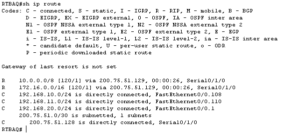
RESUMEN DOCUMENTACION IP RED DE BARRANQUILLA

Capture


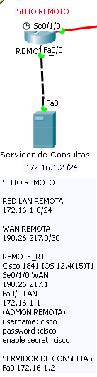
CONFIGURACION ROUTER SITIO REMOTO

hostname REMOTE_RT

enable secret cisco

username cisco password 0 cisco

CONFIGURAMOS LA INTERFAZ LAN QUE CONECTARA CON EL SERVIDOR DE CONSULTAS

interface FastEthernet0/0

ip address 172.16.1.1 255.255.255.0

duplex auto

speed auto

CONFIGURAMOS LA INTERFAZ SERIAL WAN HACIA BOGOTA

interface Serial0/1/0

ip address 190.26.217.1 255.255.255.252

clock rate 2000000

!

interface Vlan1

no ip address

shutdown

CONFIGURAMOS EL ENRUTAMIENTO ESTATICO EN ESTE RT. INDICAMOS LAS RUTAS DE TODAS LAS REDES VLAN Y REDES WAN DE LA RED, CON EL FIN DE QUE EL ROUTER SEPA COMO RESPONDER A LOS PAQUETES QUE RECIBE

ip route 10.30.1.0 255.255.255.0 190.26.217.2

ip route 10.30.0.0 255.255.255.0 190.26.217.2

ip route 10.30.2.0 255.255.255.0 190.26.217.2

ip route 10.30.4.0 255.255.255.0 190.26.217.2

ip route 10.30.6.0 255.255.255.0 190.26.217.2

ip route 10.30.8.0 255.255.255.0 190.26.217.2

ip route 10.30.10.0 255.255.255.0 190.26.217.2

ip route 200.75.51.128 255.255.255.252 192.26.217.2

ip route 192.168.10.0 255.255.255.0 190.26.217.2

ip route 192.168.11.0 255.255.255.0 190.26.217.2

ip route 10.30.3.0 255.255.255.0 190.26.217.2

CONFIGURAMOS EL ACCESOO REMOTO

banner login ^C RT REMOTO C

<<**BIENVENIDO RONALD REALES AL RT REMOTO**>> C

^C

banner motd ^CT^C

!

line vty 0 4

password cisco

login local


ESTA ES LA TABLA DE ENRUTAMIENTO QUE TENDRA EL ROUTER REMOTO AL FINALIZAR EL EJERCICIO:

Capture


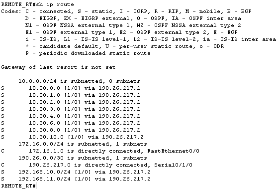
RESUMEN DIRECCIONAMIENTO IP SITIO REMOTO

Capture


ESPERO QUE LES SIRVA DE GUIA PARA SUS LABORATORIOS. NO OLVIDEN DEJAR SUS COMENTARIOS!

SALUDOS!

RONALD REALES CISCO CCNA 10833138

Resumen Practico Como funciona el Enrutamiento IP Estatico!


(Fuente: How to master CCNA All contents copyright C 2002-2013 by René Molenaar.)

IP Routing

First of all…what is a router or what is routing exactly? A switch «switches» and a router «routes» but what does this exactly mean?

We have seen switches and you have learned that they «switch» based on MAC address information. The only concern for our switch is to know when an Ethernet frame enters one of its interfaces where it should send this Ethernet frame by looking at the destination MAC address. Switches make decisions based on Data Link layer information (layer 2).

Routers have a similar task but this time we are going to look at IP packets and as you might recall IP is on the Network layer (layer 3). Routers look at the destination IP
address in an IP packet and send it out the correct interface.

Maybe you are thinking…what is the big difference here? Why don‟t we use MAC addresses everywhere and switch? Why do we need to look at IP addresses and route? Both MAC addresses and IP addresses are unique per network device. Good question and I‟m going to show you a picture to answer this:

We have two switches and to each switch are 200 computers connected. Now if all 400 computers want to communicate with each switch has to learn 400 MAC addresses. The need to know the MAC addresses of the computers on the left and right side.

Now think about a really large network…for example the Internet. There are millions of devices! Would it be possible to have millions of entries in your MAC-address table? For each device on the Internet? No way!

The problem with switching is that it‟s not scalable; we don‟t have any hierarchy just flat 48-bit MAC addresses. Let‟s look at the same example but now we are using routers.

What we have here is our 200 computers on the left are connected to router A and in the

192.168.1.0 /24 network. Router B has 200 computers behind it and the network we use over there is 192.168.2.0 /24.

Routers «route» based on IP information, in our example Router A only has to know that network 192.168.2.0 /24 is behind Router B. Router B only needs to know that the 192.168.1.0 /24 network is behind Router A.

Are you following me here? Instead of having a MAC-address-table with 400 MAC addresses we now only need a single entry on each router for each other‟s networks.

Switches use mac address tables to forward Ethernet frames and routers use a routing
table to learn where to forward IP packets to.

As soon as you take a brand new router out of the box It will build a routing table but the only information you‟ll find are the directly connected interfaces.

Let‟s start with a simple example:

Above we have one router and two computers:

  • ComputerA has IP address 192.168.1.1 and has configured IP address

    192.168.1.254 as its default gateway.

  • ComputerB has IP address 192.168.2.2 and has configured IP address

    192.168.2.254 as its default gateway.

  • On our router we have configured IP address 192.168.1.254 on interface

    FastEthernet 0/0 and IP address 192.168.2.254 on interface FastEthernet 1/0.

  • Since we also configured a subnet mask with the IP addresses our router knows the network addresses and will store these in its routing table.

Whenever ComputerA wants to send something to ComputerB this will happen:

  1. ComputerA sends an IP packet with destination IP address 192.168.2.2.
  2. ComputerA checks its own IP address and subnet mask and concludes that 192.168.2.2 is in another subnet. As a result it will forward the IP packet to its default gateway.
  3. The router receives the IP packet, checks the destination IP address and scans the routing table. IP address 192.168.2.2 matches the 192.168.2.0 /24 entry and the router will forward the IP packet out if its FastEthernet 1/0 interface.
  4. ComputerB receives the IP packet and life is good!

Are you following me so far? Let‟s configure this scenario on a real router to see what it looks like.

First I‟ll show you the configuration of the computers:

C:\Documents and Settings\ComputerA>ipconfig
 

Windows IP Configuration

Ethernet adapter Local Area Connection:

Connection-specific DNS Suffix . :

IP Address. . . . . . . . . . . . : 192.168.1.1

Subnet Mask . . . . . . . . . . . : 255.255.255.0

Default Gateway . . . . . . . . . : 192.168.1.254

C:\Documents and Settings\ComputerB>ipconfig
 

Windows IP Configuration

Ethernet adapter Local Area Connection:

Connection-specific DNS Suffix . :

IP Address. . . . . . . . . . . . : 192.168.2.2

Subnet Mask . . . . . . . . . . . : 255.255.255.0

Default Gateway . . . . . . . . . : 192.168.2.254

Above you see the IP addresses and the default gateways. Let‟s configure our router:

Router(config)#interface fastEthernet 0/0

Router(config-if)#no shutdown

Router(config-if)#ip address 192.168.1.254 255.255.255.0

Router(config-if)#exit

Router(config)#interface FastEthernet 1/0

Router(config-if)#no shutdown

Router(config-if)#ip address 192.168.2.254 255.255.255.0

I will configure the IP addresses on the interfaces, that‟s it. Now we can check the routing table:

R1#show ip route
Codes: C – connected, S – static, R – RIP, M – mobile, B – BGP

D – EIGRP, EX – EIGRP external, O – OSPF, IA – OSPF inter area

N1 – OSPF NSSA external type 1, N2 – OSPF NSSA external type 2 E1 – OSPF external type 1, E2 – OSPF external type 2 i – IS-IS, su – IS-IS summary, L1 – IS-IS level-1, L2 – IS-IS level ia – IS-IS inter area, * – candidate default, U – per-user static o – ODR, P – periodic downloaded static route


Gateway of last resort is not set


C 192.168.1.0/24 is directly connected, FastEthernet0/0

C 192.168.2.0/24 is directly connected, FastEthernet1/0

As you can see the router knows about both directly connected networks.

Let‟s see if we can ping from ComputerA to ComputerB:

C:\Users\ComputerA>ping 192.168.2.2
 

Pinging 192.168.2.2 with 32 bytes of data:

Reply from 192.168.2.2: bytes=32 time<1ms TTL=128

Reply from 192.168.2.2: bytes=32 time<1ms TTL=128

Reply from 192.168.2.2: bytes=32 time<1ms TTL=128

Reply from 192.168.2.2: bytes=32 time<1ms TTL=128


Ping statistics for 192.168.2.2:

Packets: Sent = 4, Received = 4, Lost = 0 (0% loss),

Approximate round trip times in milli-seconds: Minimum = 0ms, Maximum = 0ms, Average = 0ms

Excellent the ping is working! We just successfully routed our first IP packet 

Be aware that when you try to ping from one Windows computer to another that
your firewall might be blocking ICMP traffic…

If you are reaching some server on the Internet you are going through a lot of routers to reach your destination. If you want you can see through which routers your IP packets are traveling in order to reach the destination. You can do this with traceroute. This is what it looks like if I want to reach

www.cisco.com
from my computer:

C:\Users\Computer>tracert www.cisco.com
 

Tracing route to e144.dscb.akamaiedge.net [95.100.128.170] over a maximum of 30 hops:


  1. <1 ms <1 ms <1 ms 192.168.154.2
  2. <1 ms <1 ms <1 ms 192.168.81.254
  3. 9 ms     7 ms     9 ms 10.224.124.1
  4. 8 ms     7 ms 10 ms tb-rc0001-cr101-irb-201.core.as9143.net [213.51.150.129]
  5. 31 ms 10 ms 13 ms asd-lc0006-cr101-ae5-0.core.as9143.net [213.51.158.18]
  6. 11 ms 12 ms 11 ms ae1.ams10.ip4.tinet.net [77.67.64.61]
  7. 11 ms 14 ms 14 ms r22.amstnl02.nl.bb.gin.ntt.net [195.69.144.36]
  8. 14 ms 15 ms 11 ms ae-2.r03.amstnl02.nl.bb.gin.ntt.net [129.250.2.211] 9 14 ms 11 ms 11 ms 81.20.67.150 10 12 ms 11 ms 11 ms 95.100.128.170


Trace complete.

Above you can see that I travel through 10 routers in order to reach

www.cisco.com. You‟ll see the IP addresses of the routers and my computer also did a hostname lookup so you‟ll see the router names. Traceroute uses the ICMP protocol.

Traceroute can also be used on Cisco routers. Just type the traceroute command
and the IP address you want to reach.

Many pages ago when we talked about VLANs I explained to you how computers in different VLANs are able to communicate with each other. We can do this with a router on a stick but back then I didn‟t show you the configuration because we didn‟t talk about routers yet.

Now you know how a router works, let‟s take a look at the configuration. Here‟s the picture:

On the switch we have VLAN 10 and VLAN 20 and there‟s only a single cable between the router and switch. The router needs access to both VLANs so the link between the router and switch will be a trunk!

You can pick any number that you like but I decided to use the VLAN numbers, one sub- interface for VLAN 10 and another for VLAN 20.

Here‟s what the configuration looks like on the router:

R1(config)#interface fastEthernet 0/0

R1(config-if)#no shutdown R1(config-if)#exit


R1(config)#interface fastEthernet 0/0.10

R1(config-subif)#encapsulation dot1Q 10

R1(config-subif)#ip address 192.168.10.254 255.255.255.0

R1(config-subif)#exit


R1(config)#interface fastEthernet 0/0.20

R1(config-subif)#encapsulation dot1Q 20

R1(config-subif)#ip address 192.168.20.254 255.255.255.0

Above you can see my two sub-interfaces and the IP addresses that I assigned to them. IP address 192.168.10.254 will be the default gateway for computers in VLAN 10 and 192.168.20.254 for computers in VLAN 20.

One important command is the encapsulation dot1Q. There is no way for our router to know which VLAN belongs to which sub-interface so we have to use this command. Fa0/0.10 will belong to VLAN 10 and Fa0/0.20 to VLAN 20. Let‟s check the routing table:

R1#show ip route
Codes: C – connected, S – static, R – RIP, M – mobile, B – BGP

D – EIGRP, EX – EIGRP external, O – OSPF, IA – OSPF inter area

N1 – OSPF NSSA external type 1, N2 – OSPF NSSA external type 2 E1 – OSPF external type 1, E2 – OSPF external type 2

i – IS-IS, su – IS-IS summary, L1 – IS-IS level-1, L2 – IS-IS level ia – IS-IS inter area, * – candidate default, U – per-user static o – ODR, P – periodic downloaded static route


Gateway of last resort is not set


C 192.168.10.0/24 is directly connected, FastEthernet0/0.10

C 192.168.20.0/24 is directly connected, FastEthernet0/0.20

You can see both sub-interfaces in the routing table. This allows the router to route between the two VLANs.

Now let‟s move on to another routing scenario. This time we have two routers:

We have two routers called router Spade and router Hearts. If we look at their routing table this is what you will find:

Router Spade has two interfaces, FastEthernet 0/0 and FastEthernet 1/0 . Network 1.1.1.0 /24 has been configured on FastEthernet 0/0 and 192.168.12.0 /24 is configured on FastEthernet 1/0.

Router Hearts also has two interfaces, FastEthernet 0/0 and FastEthernet 1/0. Network 2.2.2.0 /24 has been configured on FastEthernet 0/0 and 192.168.12.0 /24 has been configured on FastEthernet 1/0.

One of the differences between routers and switches is that we configure an unique IP address on each interface that the router has.

Both routers have this routing table with only their directly connected interfaces. You can see that they stored this information in their routing table.

Now the trick is that router Spade wants to know about the 2.2.2.0 /24 network behind router Hearts. Router Hearts wants to know about the 1.1.1.0 /24 network behind router Spade. This information has to make it into the routing table somehow.

Now the big question is…how do router Spade and router Hearts know that there is a network behind each other? There are 2 ways how they can learn this information:

  • Static Routing
  • Dynamic Routing

If you use static routing you will have to do everything by yourself. YOU tell the router where to send IP packets for a certain network, this might be entertaining but it‟s a lot of work. Dynamic routing means we use a routing protocol that will exchange network information between routers. Let‟s start with a configuration example of static routes on some real routers:


Look at the network in the picture above. We have a network with two sites, headquarters and a branch office.

The headquarters is connected to the Branch office. Behind the branch office is a network with the 2.2.2.0 /24 network. We want to make sure that the headquarters can reach the

2.2.2.0 /24 network.

Let me show you how we configure this network using a static route:

Headquarters>enable

Headquarters#configure terminal

First I‟ll go to enable mode and enter configuration mode.

Headquarters(config)#interface FastEthernet 0/0

Headquarters(config-if)#no shutdown

Headquarters(config-if)#ip address 192.168.12.1 255.255.255.0

Branch>enable Branch#configure terminal

Branch(config)#interface fastEthernet0/0

Branch(config-if)#no shutdown

Branch(config-if)#ip address 192.168.12.2 255.255.255.0

Branch(config-if)#exit

Branch(config)#interface fastEthernet 1/0

Branch(config-if)#no shutdown

Branch(config-if)#ip address 2.2.2.2 255.255.255.0

Then I‟ll configure the IP addresses on the interfaces; don‟t forget to do a «no shutdown» on the interfaces.

Let‟s take a look at the routing tables of both routers:

Headquarters#show ip route

Codes: C – connected, S – static, R – RIP, M – mobile, B – BGP

D – EIGRP, EX – EIGRP external, O – OSPF, IA – OSPF inter area

N1 – OSPF NSSA external type 1, N2 – OSPF NSSA external type 2

E1 – OSPF external type 1, E2 – OSPF external type 2 i – IS-IS, su – IS-IS summary, L1 – IS-IS level-1, ia – IS-IS inter area, * – candidate default, o – ODR, P – periodic downloaded static route


Gateway of last resort is not set


C 192.168.12.0/24 is directly connected, FastEthernet0/0
Branch#show ip route

Codes: C – connected, S – static, R – RIP, M – mobile, B – BGP

D – EIGRP, EX – EIGRP external, O – OSPF, IA – OSPF inter area

N1 – OSPF NSSA external type 1, N2 – OSPF NSSA external type 2

E1 – OSPF external type 1, E2 – OSPF external type 2 i – IS-IS, su – IS-IS summary, L1 – IS-IS level-1, o – ODR, P – periodic downloaded static route


Gateway of last resort is not set


C 192.168.12.0/24 is directly connected, FastEthernet0/0

2.0.0.0/24 is subnetted, 1 subnets

C     2.2.2.0 is directly connected, FastEthernet1/0

Use the show ip route command to view the routing table. This is what a router uses to make decisions where to forward IP packets to. By default a router only knows its directly connected networks. We configured an IP address with a subnet mask on the interface so the router also knows the network address.

  • Router Headquarters knows about network 192.168.12.0/24.
  • Router Branch knows about network 192.168.12.0/24 and 2.2.2.0/24.

At this moment our Headquarters router has no idea how to reach network 2.2.2.0/24 because there is no entry in the routing table. What will happen when we try to reach it?

Let‟s check:

Headquarters#ping 2.2.2.2


Type escape sequence to abort.

Sending 5, 100-byte ICMP Echos to 2.2.2.2, timeout is 2 seconds: ….. Success rate is 0 percent (0/5)

The ping will fail. This router checks its routing table, discovers that it doesn‟t know how to reach network 2.2.2.0 /24 and will drop the traffic.

Let‟s use a static route to tell router Headquarters how to reach this network!

Headquarters(config)#ip route 2.2.2.0 255.255.255.0 192.168.12.2

We use the ip route command to create a static route. Let me break it down for you:

  • 2.2.2.0 is the network we want to reach.
  • 255.255.255.0 is the subnet mask of the network.
  • 192.168.12.2 is called the next hop IP address. It‟s the IP address where we want to send traffic to. In this example that‟s the branch router.

I‟m telling router Headquarters that it can reach network 2.2.2.0 /24 by sending traffic to IP address 192.168.12.2 (the Branch router).

Let‟s take another look at the routing table to see if anything has changed:

Headquarters#show ip route

Codes: C – connected, S – static, R – RIP, M – mobile, B – BGP

D – EIGRP, EX – EIGRP external, O – OSPF, IA – OSPF inter area

N1 – OSPF NSSA external type 1, N2 – OSPF NSSA external type 2 E1 – OSPF external type 1, E2 – OSPF external type 2

i – IS-IS, su – IS-IS summary, L1 – IS-IS level-1, L2 -IS-IS inter area, * – candidate default, U – per-user static route o – ODR, P – periodic downloaded static route


Gateway of last resort is not set


C 192.168.12.0/24 is directly connected, FastEthernet1/0

1.0.0.0/24 is subnetted, 1 subnets

C     1.2.3.0 is directly connected, FastEthernet0/0

2.0.0.0/24 is subnetted, 1 subnets

S     2.2.2.0 [1/0] via 192.168.12.2

We can now see an entry for network 2.2.2.0/24 in our routing table. Whenever router Headquarters has traffic for network 2.2.2.0 /24 it will send it to IP address 192.168.12.2 (router Branch). Let‟s see if our ping is now working:

Headquarters#ping 2.2.2.2

Type escape sequence to abort.

Sending 5, 100-byte ICMP Echos to 2.2.2.2, timeout is 2 seconds:

!!!!!

Success rate is 100 percent (5/5), round-trip min/avg/max = 4/5/12 ms

Bingo now it‟s working. Router Headquarters knows how to reach network 2.2.2.0 /24 because of our static route.

Are you following me so far? Whenever an IP packet arrives at a router it will check its routing table to see if it knows about the destination network. If it does it will forward the IP packet and if it has no idea where to send traffic it will drop the IP packet.

There is another situation where a static route might be useful, let me demonstrate another network:

In the picture above our Headquarters router is connected to an ISP (Internet Service Provider). There are many networks on the Internet so do we require all of those networks on the Internet in our routing table? The answer is no because we can use a default route, let me show you what it is:

Headquarters(config)#interface fastEthernet 1/0

Headquarters(config-if)#ip address 1.2.3.2 255.255.255.0

Headquarters(config-if)#no shutdown Headquarters(config-if)#exit

First we‟ll configure an IP address on the Fastethernet 1/0 of the headquarters router.

Headquarters#ping 1.2.3.1

Type escape sequence to abort.

Sending 5, 100-byte ICMP Echos to 1.2.3.1, timeout is 2 seconds:

!!!!!

Success rate is 100 percent (5/5), round-trip min/avg/max = 4/5/12 ms

It‟s always a good idea to check connectivity. A quick ping to the ISP router proves that we can reach the ISP.

Headquarters#show ip route

Codes: C – connected, S – static, R – RIP, M – mobile, B – BGP

D – EIGRP, EX – EIGRP external, O – OSPF, IA – OSPF inter area

N1 – OSPF NSSA external type 1, N2 – OSPF NSSA external type 2 E1 – OSPF external type 1, E2 – OSPF external type 2

i – IS-IS, su – IS-IS summary, L1 – IS-IS level-1, L2 -IS-IS inter area, * – candidate default, U – per-user static route o – ODR, P – periodic downloaded static route


Gateway of last resort is not set


C     1.2.3.0 is directly connected, FastEthernet1/0

Right now the Headquarters router only knows how to reach network 1.2.3.0/24 because it‟s directly connected.

Let‟s configure a default route so that we can reach the Internet:

Headquarters(config)#ip route 0.0.0.0 0.0.0.0 1.2.3.1

Let me explain this one:

  • The first 0.0.0.0 is the network address; in this case it means all networks.
  • The second 0.0.0.0 is the subnet mask; all 0s means all subnet masks.
  • 1.2.3.1 is the next hop IP address. In this case the IP address of the ISP router.

In other words, this static route will match all networks and that‟s why we call it a default route. When our router doesn‟t know where to deliver IP packets to, we‟ll throw it over the fence towards the ISP and it will be their job to deliver it…sounds good right?

Something important to know about routers is that they always will use the most specific
match in their routing table. Let me give you an example:

Router#show ip route static

192.168.1.0/24 is variably subnetted, 2 subnets, 2 masks

S     192.168.1.0/24 [1/0] via 10.2.2.2

S     192.168.1.128/25 [1/0] via 10.3.3.2

S 192.168.0.0/16 [1/0] via 10.1.1.2

Imagine the router above receives an IP packet with destination IP address 192.168.1.140. Will it send the IP packet towards 10.2.2.2, 10.3.3.2 or 10.1.1.2?

All 3 entries in the routing table match this destination IP address but in this case 192.168.1.128 /25 is the most specific entry. The IP packets will be forwarded to 10.3.3.2.


EJERCICIO COMPLETO INTERVLAN ROUTING-VTP-STP-SUBNET-VLAN


Configuracion en el Router 0 que enruta el trafico entre las Vlans (subredes)

username cisco password cisco

banner login ^C ESTE COMANDO ES PARA COLOCAR EL MENSAJE DE BIENVENIDA EN EL ROUTER

ACCESO PERMITIDO SOLO A PERSONAL AUTORIZADO

^C

line con 0

password cisco

login local ESTE COMANDO PERMITE QUE CUANDO NOS CONECTEMOS SOLICITE USUARIO Y PASS

line vty 0 15

password cisco

login local


CONFIGURACION DE ENRUTAMIENTO ENTRE VLANS (INTERVLAN ROUTING)

DEBEMOS UTILIZAR El COMANDO ¨NO IP ADDRESS¨ EN LA INTERFAZ FISICA PUES ESTA NO TENDRA IP, SOLO SUBINTERFACES. SE DEBEN CREAR 7 SUB INTERFACES LOGICAS UNA PARA CADA VLAN

interface GigabitEthernet0/0

no ip address

no shutdown

!

SE CREA LA SUBINTERFAZ PARA LA PRIMERA SUBRED UTILIZANDO LA ULTIMA IP UTILIZABLE DE LA SUBRED CORRESPONDIENTE, ESTA ES LA IP QUE SE DEBE COLOCAR COMO GATEWAY EN LOS HOSTS

SE DEBE ENCAPSULAR CON EL NUMERO DE LA VLAN

interface GigabitEthernet0/0.1

encapsulation dot1Q 100

ip address 192.168.110.126 255.255.255.128

!

interface GigabitEthernet0/0.2

encapsulation dot1Q 200

ip address 192.168.110.254 255.255.255.128

!

interface GigabitEthernet0/0.3

encapsulation dot1Q 300

ip address 172.16.0.30 255.255.255.224

!

interface GigabitEthernet0/0.4

encapsulation dot1Q 400

ip address 172.17.0.62 255.255.255.224

!

interface GigabitEthernet0/0.5

encapsulation dot1Q 500

ip address 10.10.10.14 255.255.255.240

!

interface GigabitEthernet0/0.6

encapsulation dot1Q 600

ip address 10.10.10.30 255.255.255.240

!

ESTA SERA LA SUBINTERFAZ PARA LA VLAN DE ADMINISTRACION, QUE NOS PERMITIRA ACCEDER A LOS DISPOSITIVOS DE RED DESDE CUALQUIER HOST SWITCH O ROUTER UTILIZANDO TELNET

interface GigabitEthernet0/0.7

description VLAN ADMINISTRACION

encapsulation dot1Q 50

ip address 192.168.1.1 255.255.255.0


Configuracion en el Switch 0 Que actua como servidor VTP


username cisco password cisco

banner motd ^C

ACCESO PERMITIDO SOLO A PERSONAL AUTORIZADO ^C

^C

line con 0

password cisco

login local

line vty 0 15

password cisco

login local

CONFIGURACION VTP SERVER

Vtp mode server

Vtp domain clase.edu

Vtp password sena1234


SE CREAN LAS VLAN EN ESTE SWITCH QUE ES EL RAIZ

Vlan 50

Name administracion

Vlan 100

Name directivos

Vlan 200

Name invitados

Vlan 300

Name tecnologia

Vlan 400

Name pruebas4

Vlan 500

Name pruebas5

Vlan 600

Name pruebas6

!

SE CONFIGURAN LAS INTERFACES QUE CONECTAN AL ROUTER Y OTROS SWITCH EN MODO TRUNKING

interface FastEthernet0/1

switchport mode trunk

!

interface FastEthernet0/2

switchport mode trunk

!

SE DEBE DEFINIR UNA IP DE ADMINISTRACION PARA ESTE SW EN ESTA VLAN QUE ES LA QUE SE UTILIZA PARA ADMON REMOTA.

interface Vlan50

ip address 192.168.1.2 255.255.255.0

!

ip default-gateway 192.168.1.1

SE DEBE DEFINIR UN DEFAULT GATEWAY PARA QUE EL SW SEPA DONDE ENVIAR LAS RESPUESTAS A LAS SOLICITUDES TELNET DESDE CUALQUIER VLAN (SUBNET) EN ESTE CASO SE COLOCA LA IP DE ADMINISTRACION DEL ROUTER


Configuracion en el Switch 1 Que esta en modo transparente

!

username cisco password cisco

banner motd ^C

ACCESO PERMITIDO SOLO A PERSONAL AUTORIZADO ^C

!

line con 0

password cisco

login local

line vty 0 15

password cisco

login local

!

CONFIGURACION VTP TRANSPARENTE

vtp mode transparent

!

COMO ESTE SW ESTA EN MODO TRANSPARENTE Y NO APRENDE VLANS SE DEBE CREAR MANUALMENTE LA VLAN DE ADMINISTRACION Y DEFINIRLE LA IP DE ADMON A ESTE SW Y SU DEFAULT GATEWAY.

vlan 50

name administracion

!

interface Vlan50

ip address 192.168.1.3 255.255.255.0

!

ip default-gateway 192.168.1.1

!

SE CONFIGURAN LAS INTERFACES QUE CONECTAN AL ROUTER Y OTROS SWITCH EN MODO TRUNKING

interface FastEthernet0/1

switchport mode trunk

!

interface FastEthernet0/2

switchport mode trunk

!


Configuracion switch2 en modo cliente para Subredes VLAN 100 y 200


username cisco password cisco

!

banner motd ^C

ACCESO PERMITIDO SOLO A PERSONAL AUTORIZADO ^C

!

line con 0

password cisco

login local

line vty 0 15

password cisco

login local

!

CONFIGURACION VTP CLIENTE

Vtp mode client

Vtp domain clase.edu

Vtp password sena1234


SE OPTIMIZA EL SPANNING TREE DE ACUERDO A LOS REQUERIMIENTOS PLANTEADOS EN EL EJERCICIO PARA CADA VLAN, EL ROOT SWITCH NO CAMBIA SOLO CAMBIA LA RUTA PARA EL TRAFICO VLAN.

#spanning-tree vlan 300 root primary

#spanning-tree vlan 100 root secondary


SE CONFIGURAN LAS INTERFACES QUE CONECTAN A OTROS SWITCH EN MODO TRUNKING

interface FastEthernet0/1

switchport mode trunk

!

SE CONFIGURAN LAS INTERFACES QUE CONECTAN A LOS HOST EN MODO ACCESSO INDICANCO A QUE VLAN PERTENECEN

interface FastEthernet0/2

switchport access vlan 200

!

interface FastEthernet0/3

switchport access vlan 100

!

SE CONFIGURA LA IP DE ADMINISTRACION Y DEFAULT GATEWAY


interface Vlan50

ip address 192.168.1.4 255.255.255.0

!

ip default-gateway 192.168.1.1


Configuracion switch4 en modo cliente para Subredes VLAN 300 y 400

username cisco password cisco

banner motd ^C

ACCESO PERMITIDO SOLO A PERSONAL AUTORIZADO ^C

!

line con 0

password cisco

login local

line vty 0 15

password cisco

login local

!

Vtp mode client

Vtp domain clase.edu

Vtp password sena1234

!

#spanning-tree vlan 100 root primary

#spanning-tree vlan 200 root secondary

!

interface FastEthernet0/1

switchport mode trunk

!

interface FastEthernet0/2

switchport mode trunk

!

interface FastEthernet0/3

switchport mode trunk

!

interface FastEthernet0/4

switchport access vlan 300

!

interface FastEthernet0/5

switchport access vlan 400

!

interface Vlan50

ip address 192.168.1.5 255.255.255.0

!

ip default-gateway 192.168.1.1

!

Configuracion switch3 en modo cliente para Subredes VLAN 500 y 600

username cisco privilege 1 password 0 cisco

banner motd ^C

ACCESO SOLO A PERSONAL AUTORIZADO ^C

line con 0

password cisco

login local

!

line vty 0 15

password cisco

login local

!

Vtp mode client

Vtp domain clase.edu

Vtp password sena1234

!

#spanning-tree vlan 200 root primary

#spanning-tree vlan 300 root secondary

!

interface FastEthernet0/1

switchport mode trunk

!

interface FastEthernet0/2

switchport access vlan 500

!

interface FastEthernet0/3

switchport access vlan 600

!

interface Vlan50

ip address 192.168.1.6 255.255.255.0

!

ip default-gateway 192.168.1.1


DIRECCIONAMIENTO IPV6


A principios de los años noventa, el grupo de trabajo de ingeniería de Internet (IETF) centró su interés en el agotamiento de direcciones de red IPv4 y comenzó a buscar un reemplazo para este protocolo. Esta actividad produjo el desarrollo de lo que hoy se conoce como IPv6.

Crear mayores capacidades de direccionamiento fue la motivación inicial para el desarrollo de este nuevo protocolo. También se consideraron otros temas durante el desarrollo de IPv6, como:

Mejor manejo de paquetes

Escalabilidad y longevidad mejoradas

Mecanismos de QoS

Seguridad integrada


Para proporcionar estas características, IPv6 ofrece:

Direccionamiento jerárquico de 128 bits: para expandir las capacidades de direccionamiento

Simplificación del formato de encabezado: para mejorar el manejo de paquetes

Soporte mejorado para extensiones y opciones: para escalabilidad y longevidad mejoradas y mejor manejo de paquetes

Capacidad de etiquetado de flujo: como mecanismos QoS

Capacidades de autenticación y privacidad: para integrar la seguridad


Usa 128 bits en vez de 32

16 bytes (2 caracteres son un byte)


version = 6

lleva implicita la autenticacion

no incluye el checksum de ipv4

mas eficiente

mejor control de trafico


64 bits para redes 64 bits para host /64

a cisco no le interesa lo que la RFC dice

los (ceros) se reemplazan con puntos :: (solo una vez)

los primeros ceros se omiten


No existen Clases

No existe Broadcast como tal


Existen 3 tipos: Unicast de host a host

multicast: un host a varios host

Anycast:un broadcast a la interfaz mas cercana.


Tipos

global Unicast (Dir Publico) 2000 hasta 3FFF

Site local(Dir Privado):FECO

Link local (Dir especial para host directamente conectados) FE80

Multicast: empiezan con FF


Multicast Address

FF01:0000:0000:1 (BROADCAST)MULTICAST A TODOS LOS NODOS

FF02:0000:0000:1 LINK LOCAL ALL NODES

FF01::2 INTERFACE LOCAL ALL ROUTERS

FF02::2 LINK LOCAL ALL ROUTERS

FF02::5 LINK LOCAL ALL ROUTERS RUNNING OSPFV3

FF02::6 LINK LOCAL ALL ROUTERS RUMMING DR/DBR OSPFV3

FF02::9 ALL ROUTERS RUNNING RIP


Se puede configurar de 4 formas:

Manual

EUI-64, convierte la MAC en HOst

DHCP: combian ipv4 e ipv6

Stateless auto: entrega IPS sin ser serverDHCP


La Mascara es /64 segun la RFC

La IPV6 se forma desde la MAC que es de 48bits

como?

Usando el EUI-64 Se invierte el 7mo bit

Ejemplo:

MAC 16be.163f.873a (Dir IPV4)


16 en bits 0001.0110

Se invierte el 7mo bit: 0001.0100

queda: 14be.163f.873a

luego se inserta FFFE

Queda: 14be:16FF:FE3f:873a (Dir IPV6)


No maneja ARP lo reemplaza ICMPv6ND


Para configurar una IPV6 usando Stateless autoconf este se conoce como DHCP lite

La parte de red es por defecto la del enrutador

Como Host utiliza la MAC Address modificada

Por lo anterior no necesita un Sevidor DHCP pues la crea a partir de la direccion del router y su MAC fisica.

usando RS(host la pide) y RA (Router responde)


Ipv6 Mobility : permite conectividad alrededor de la red.


IPV6 Routing

usa rutas estaticas

RIPng (Next Generaton)

EIGRP for IPV6

BGP for IPV6

IS-IS y OSPF para Ipv6

IPv6 no es simplemente un nuevo protocolo de Capa 3: es una nueva suite de protocolos. Se han desarrollado nuevos protocolos en varias capas del stack para admitir este nuevo protocolo. Hay un nuevo protocolo de mensajería (ICMPv6) y nuevos protocolos de enrutamiento. Debido al mayor tamaño del encabezado de IPv6, también repercute en la infraestructura de red subyacente.


ANCHO DE BANDA – TASA DE TRANSFERENCIA – UNIDADES DE MEDIDA


Bit

Bit es el acrónimo Binary digit (‘dígito binario’). Un bit es un dígito del sistema de numeración binario. Las unidades de almacenamiento tienen por símbolo bit.1

Mientras que en el sistema de numeración decimal se usan diez dígitos, en el binario se usan solo dos dígitos, el 0 y el 1. Un bit o dígito binario puede representar uno de esos dos valores: 0 o1.

Se puede imaginar un bit como una bombilla que puede estar en uno de los siguientes dos estados:

apagada  o encendida 


El bit es la unidad mínima de información empleada en informática, en cualquier dispositivo digital, o en la teoría de la información. Con él, podemos representar dos valores cuales quiera, como verdadero o falso, abierto o cerrado, blanco o negro, norte o sur, masculino o femenino, rojo o azul, etc. Basta con asignar uno de esos valores al estado de «apagado» (0), y el otro al estado de «encendido» (1).


Ancho de banda

La capacidad que posee un medio de transportar datos se describe como el ancho de banda de los datos sin procesar de los medios. El ancho de banda digital mide la cantidad de información que puede fluir desde un lugar hacia otro en un período de tiempo determinado. El ancho de banda generalmente se mide en kilobits por segundo (kbps) o megabits por segundo (Mbps).

El ancho de banda práctico de una red se determina mediante una combinación de factores: las propiedades de las tecnologías y los medios físicos elegidos para señalizar y detectar señales de red.

Las propiedades de los medios físicos, las tecnologías actuales y las leyes de la física desempeñan una función al momento de determinar el ancho de banda disponible.

La figura muestra las unidades de ancho de banda de uso más frecuente.

Tasa de transferencia

La tasa de transferencia se refiere al ancho de banda real medido en un momento concreto del día empleando rutas concretas de internet mientras se transmite un conjunto específico de datos, desafortunadamente, por muchas razones la tasa es con frecuencia menor al ancho de banda máximo del medio que se está empleando.

Los siguientes son algunos de los factores que determinan la tasa de transferencia:

  • Dispositivos de Internet-Working
  • Tipos de datos que se van a transferir
  • Topología de la red
  • Número de usuarios en la red
  • La computadora del usuario
  • El servidor
  • Condiciones de la energía
  • Congestión

El ancho de banda teórico de la red es una consideración importante en el diseño de la red, porque la tasa de transferencia de la red nunca es mayor que dicho ancho de banda, debido a las limitaciones puestas por el medio y a las tecnologías de red elegidas.

La unidad con que el Sistema Internacional de Unidades expresa el bit rate es el bit por segundo (bit/s, b/s, bps). La b debe escribirse siempre en minúscula, para impedir la confusión con bytepor segundo (B/s). Para convertir de bytes/s a bits/s, basta simplemente multiplicar por «8» y viceversa.

Que la unidad utilizada sea el bit/s, no implica que no puedan utilizarse múltiplos del mismo:

  • kbit/s o kbps (kb/s, kilobit/s o mil bits por segundo)
  • Mbit/s o Mbps(Mb/s, Megabit/s o un millón de bits por segundo)
  • Gbit/s o Gbps (Gb/s, Gigabit, mil millones de bits)
  • byte/s (B/s u 8 bits por segundo)
  • kilobyte/s (kB/s, mil bytes u ocho mil bits por segundo)
  • megabyte/s (MB/s, un millón de bytes u 8 millones de bit por segundo)
  • gigabyte/s (GB/s, mil millones de bytes u 8 mil millones de bits)


Rendimiento

El rendimiento es la medida de transferencia de bits a través de los medios durante un período de tiempo determinado. Debido a diferentes factores, el rendimiento generalmente no coincide con el ancho de banda especificado en las implementaciones de la capa física, como Ethernet.


Muchos factores influyen en el rendimiento. Entre estos factores se incluye la cantidad y el tipo de tráfico además de la cantidad de dispositivos de red que se encuentran en la red que se está midiendo. En una topología multiacceso como Ethernet, los nodos compiten por el acceso y la utilización de medios. Por lo tanto, el rendimiento de cada nodo se degrada a medida que aumenta el uso de los medios.


En una internetwork o una red con múltiples segmentos, el rendimiento no puede ser más rápido que el enlace más lento de la ruta de origen a destino. Incluso si todos los segmentos o gran parte de ellos tienen un ancho de banda elevado, sólo se necesita un segmento en la ruta con un rendimiento inferior para crear un cuello de botella en el rendimiento de toda la red.


Capacidad de transferencia útil


Se ha creado una tercera medida para evaluar la transferencia de datos utilizables. Dicha medición se denomina capacidad de transferencia útil. La capacidad de transferencia útil es la medida de datos utilizables transferidos durante un período de tiempo determinado. Por lo tanto, es la medida de mayor interés para los usuarios de la red.

Como se muestra en la figura, la capacidad de transferencia útil mide la transferencia efectiva de los datos del usuario entre las entidades de la capa de aplicación, por ejemplo entre el proceso de un servidor web de origen y un dispositivo con explorador web de destino.


A diferencia del rendimiento, que mide la transferencia de bits y no la transferencia de datos utilizables, la capacidad de transferencia útil considera los bits que generan la sobrecarga del protocolo. Esta capacidad representa el rendimiento sin la sobrecarga de tráfico para establecer sesiones, acuses de recibo y encapsulaciones.


Por ejemplo, considere dos hosts en una LAN que transfiere un archivo. El ancho de banda de la LAN es de 100 Mbps. Debido al uso compartido y al encabezado de los medios, el rendimiento entre los equipos es solamente de 60 mbps. Con una sobrecarga del proceso de encapsulación de stack TCP/IP, la velocidad real de los datos recibidos por la computadora de destino, es decir la capacidad de transferencia útil, es sólo de 40 Mbps.


Tipos de medios físicos

La capa física se ocupa de la señalización y los medios de red. Esta capa produce la representación y agrupación de bits en voltajes, radiofrecuencia e impulsos de luz. Muchas organizaciones que establecen estándares han contribuido con la definición de las propiedades mecánicas, eléctricas y físicas de los medios disponibles para diferentes comunicaciones de datos. Estas especificaciones garantizan que los cables y los conectores funcionen según lo previsto mediante diferentes implementaciones de la capa de enlace de datos.


Por ejemplo, los estándares para los medios de cobre se definen según lo siguiente:

Tipo de cableado de cobre utilizado

Ancho de banda de la comunicación

Tipo de conectores utilizados

Diagrama de pines y códigos de colores de las conexiones a los medios

Distancia máxima de los medios.

La figura muestra algunas de las características de los medios de networking.

Esta sección también describirá algunas de las características importantes de los medios inalámbricos, ópticos y de cobre comúnmente utilizados.

Tipos de cables UTP


El cableado UTP, con una terminación de conectores RJ-45, es un medio común basado en cobre para interconectar dispositivos de red, como computadoras, y dispositivos intermediarios, como routers y switches de red.

Según las diferentes situaciones, es posible que los cables UTP necesiten armarse según las diferentes convenciones para los cableados. Esto significa que los alambres individuales del cable deben conectarse en diferente orden para distintos grupos de pins en los conectores RJ-45. A continuación se mencionan los principales tipos de cables que se obtienen al utilizar convenciones específicas de cableado:

Cable directo de Ethernet

Cruzado Ethernet

Transpuesto

La figura muestra la aplicación típica de estos cables, así como también una comparación de estos tres tipos de cable.

Es posible que el uso de un cable de conexión cruzada o de conexión directa en forma incorrecta entre los dispositivos no dañe los dispositivos pero no se producirá la conectividad y la comunicación entre los dispositivos. Éste es un error común de laboratorio. Si no se logra la conectividad, la primera medida para resolver este problema es verificar que las conexiones de los dispositivos sean correctas.